Ray Tracer - Reflection and Refraction
https://gundralaa.github.io/2023/03/23/cs184-ray-reflect.html
CS184 Project 3-2
Abhinav Gundrala
Overview
The extension to the ray tracer project introduced new more complicated material-ray interactions. Previously, rays were traced in random directions from the hit point due to the uniform property of diffuse material. With materials such as perfect reflectors or refracting material however, rays are forced into a specific direction. Microfacet material represents complex material qualities that are characterized using the parameters alpha, eta and k. These parameters describe model surfaces as collections of tiny microfacets that are mirrors with properties to either reflect or refract light. All methods here describe operations performed on rays that intersect with these materials to generate incoming rays for radiance estimation.
Mirrors and Glass
Part 1
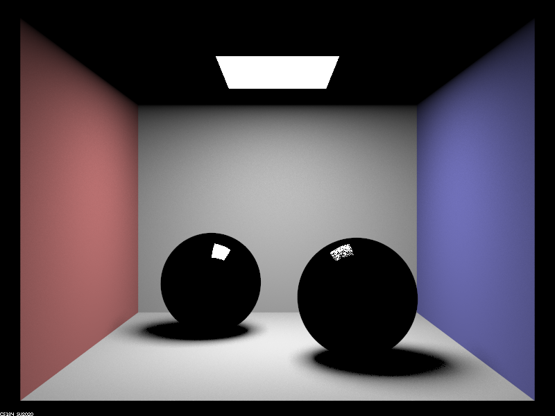
The scene below has two spheres. The back sphere is a reflective sphere using perfect reflection and the sphere in front has a glass material. The glass material implements both refractive and reflective qualities. Images were rendered with 256 samples per pixel and 4 samples per light.
Max Ray Depth 0

Max Ray Depth 1
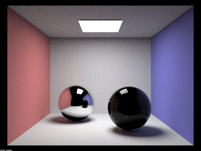
Max Ray Depth 2
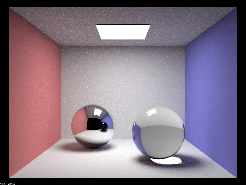
Max Ray Depth 3
Max Ray Depth 4

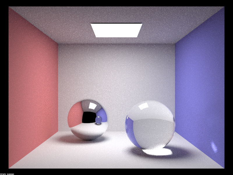
Max Ray Depth 5
Max Ray Depth 100
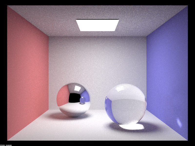
Starting with the 0 depth image, only direct lighting from light sources is displayed. These rays are directly from light to camera position. In the m=0 image we only see the cornell box light.
- m=1; 1 bounce lighting is accounted for which only includes rays that are traced from a light source to an object directly to a camera pixel. Both spheres are still not visible fully since only the specular reflective regions of the spheres trace rays directly from the light sources to the camera.
- m=2; Light can now bounce once which allows for the reflective material to be visible. All outgoing rays are traced with exactly one incoming radiance ray off the reflective surface. This extra bounce allows the one bounce estimation of other areas in the scene to trace back on to the reflective surface.
- m=3; the refractive surface is finally visible. this is due to the fact that a ray that passes through the glass sphere as is refracted must bounce once on entry and once on exit. With m=2 the exit bounce would be the last bounce and the radiance traced along the ray would be zero or black since there is no direct lighting estimation. With an extra bounce, the exit ray can intersect an area in the scene and use the radiance estimation at that point.
- m=4; the last noticeable major multibounce effect occurs here, where there is a specular mark on the wall due to refraction from the area light through the sphere reflecting off the wall.
- m=5; the image gets brighter and more light is refected off of the ceiling and wall in areas around the glass sphere and the area light.
- m=100; More refraction through the top of the glass sphere is observable and the rays of light that are diffusing off the ceiling are more prominent due to this refraction. Generally the image gets brighter but major lighting effects are minimal.
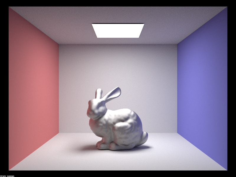
Microfacet Material
Part 2
Microfacet material models materials as surfaces with lots of tiny mirrors. The parameters eta and k determine the reflection values based on the material and the alpha value determines the spread of the outgoing vector distribution. This can be characterized as surface roughness and a higher alpha means a more diffuse surface while a lower alpha means a more reflective surface. This gives continuous control over material properties.
Alpha Images
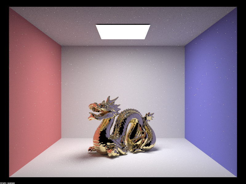
All images were rendered using 128 samples per pixel and 1 sample per light. The number of bounces was set to 5.
Alpha 0.005
Alpha 0.05
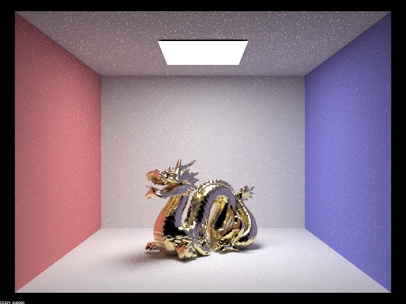
Alpha 0.25
Alpha 0.5
Observably, the images differ from the amount of reflection that occurs where an alpha=0.005 has a reflective property where the bisector distribution of incoming rays with respect to the outgoing ray on the surface is closer to surface normal. Essentially, this means the surface acts more like a reflector. When the alpha increases to alpha=0.5, the surface becomes more diffuse and the incoming rays from multiple areas in the scene contribute to the outgoing camera ray.
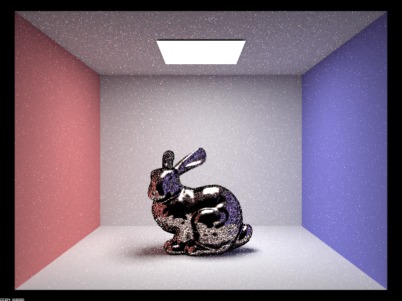
Importance Sampling
Since the microfacet ray distribution is not uniform, importance sampling can help reduce noise while allowing for the same number of samples. The images below depict the difference. Both were rendered using 64 samples per pixel, 1 sample per light and 5 bounces. The importance sampling followed the Beckman normal distribution which was parameterized using an alpha. For each outgoing ray, the h bisector vector of the outgoing and incoming ray was sampled using its polar form and the incoming ray direction was calculated using a vector difference between the outgoing and bisector.
Cosine Hemisphere Sampling
Importance Sampling
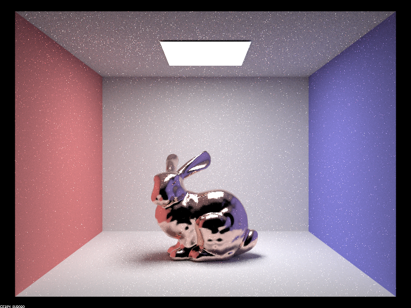
With the same number of sampled rays, a greater amount of the variance in the image was captured using importance sampling which results in a less noisy image. Essentially only ray directions that had a large probability of being incoming ray directions were sampled and used to calculate the incoming radiance which allowed for a more efficent monte carlo estimate.
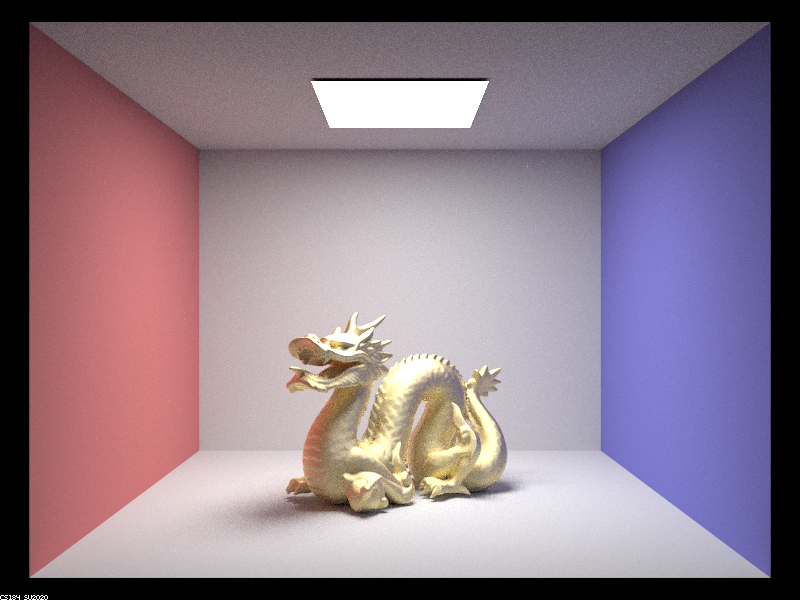
Alternative Material
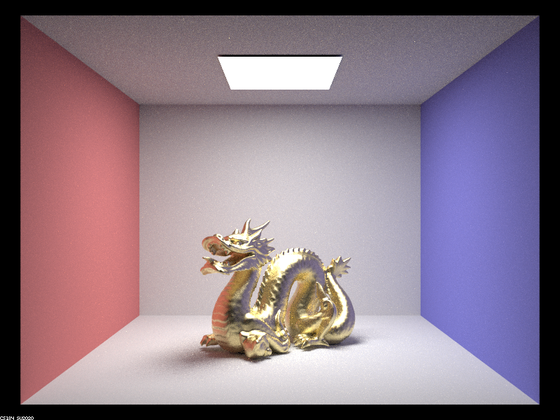
The fresnel coefficents for Iron (Fe) were used to modify the bunny material in the following image. This is the current configuration using values from online.
<microfacet>
    <alpha>0.5</alpha>
    <eta>2.8851 2.9500 2.6500</eta>
    <k>3.0449 2.9300 2.8075</k>
</microfacet>
Iron Bunny
As is noticable, the bunny is infact very iron like.